When a client or contractor asks whether a model is at LOD 300 vs LOD 400, they are really asking one question: can this be built from, or does it still need another round of detailing? LOD 300 models are precisely dimensioned and coordinated for design decisions and clash detection, while LOD 400 models carry the fabrication-level detail a shop needs to cut, bend, and install material without further interpretation. In my practice, I have watched entire coordination meetings stall because a team assumed a wall section was fabrication-ready when it was only design-development-ready. Knowing which level of development a deliverable actually sits at, rather than what the drawing set implies, is what keeps a project on schedule and off the RFI log.
What Level of Development Actually Measures
Level of development in BIM is not a measure of how much time was spent modeling or how good the render looks. It is a defined statement of reliability: at any given LOD, a specific element is guaranteed to represent certain geometric and non-geometric information, and nothing more. The BIMForum LOD Specification, the industry reference most architects and contractors work from, breaks this down element by element rather than model by model, which means a single Revit file can legitimately contain a structural frame at LOD 300 and a curtain wall system at LOD 400 simultaneously. That distinction matters because clients often assume LOD applies uniformly to the whole set. In my experience, the first coordination failure on a project usually traces back to someone reading a drawing’s polish as a proxy for its LOD, rather than checking the model element authorship notes that actually define it, as documented in the current specification at https://bimforum.org/resource/lod-level-of-development-lod-specification/.
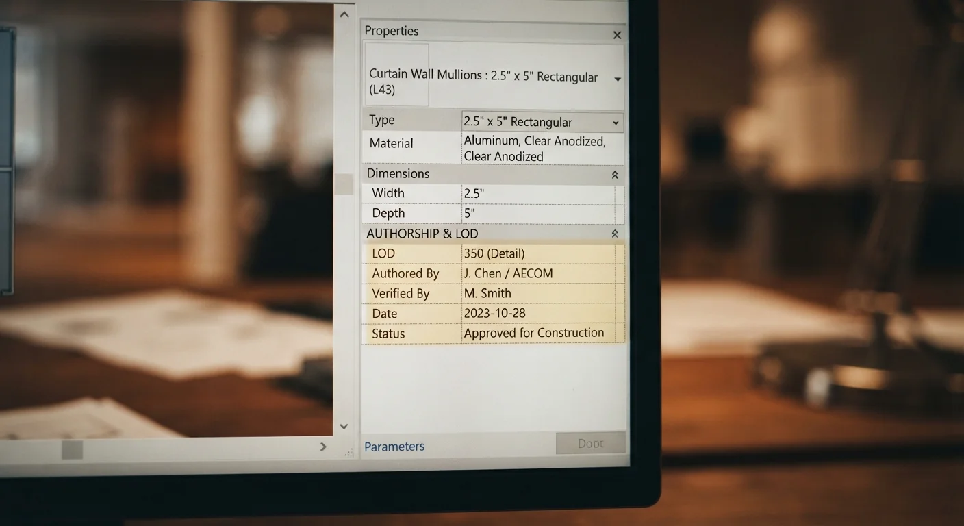
LOD 300: The Design Development Baseline
LOD 300 is where most design development sets live, and it is the level most owners picture when they hear “the model is coordinated.” Elements are modeled as specific systems with accurate size, shape, location, and orientation, and quantities, size, and location can be measured directly from the model rather than estimated. What LOD 300 does not guarantee is manufacturer-specific detail: a door is a door of the correct dimensions and swing, not yet a specific hardware set from a specific supplier. This is the level where architects finalize structural bays, confirm mechanical routing corridors, and run clash detection between disciplines with confidence that the geometry is real rather than schematic. Permit sets are frequently issued from an LOD 300 model precisely because it answers the questions a plan reviewer asks without carrying detail that has not yet been contractually locked in with a fabricator or supplier.

LOD 350: The Coordination Bridge
LOD 350 sits between design intent and construction detail, and it exists specifically to solve interfaces, not full elements. At LOD 350, an element includes the interfacing parts and connections needed to coordinate with other building systems, such as a structural connection detail or the bracket geometry where a curtain wall meets a slab edge. Contractors increasingly request LOD 350 mid-project because clash detection at LOD 300 can miss conflicts that only appear once connection hardware, clearances, and access paths are modeled. A steel beam at LOD 300 might pass every clash check against ductwork above it, then fail once the actual connection plate geometry is added at LOD 350. Requesting this level for specific trade interfaces, rather than the whole model, keeps coordination effort proportional to actual risk instead of inflating every discipline’s workload uniformly.
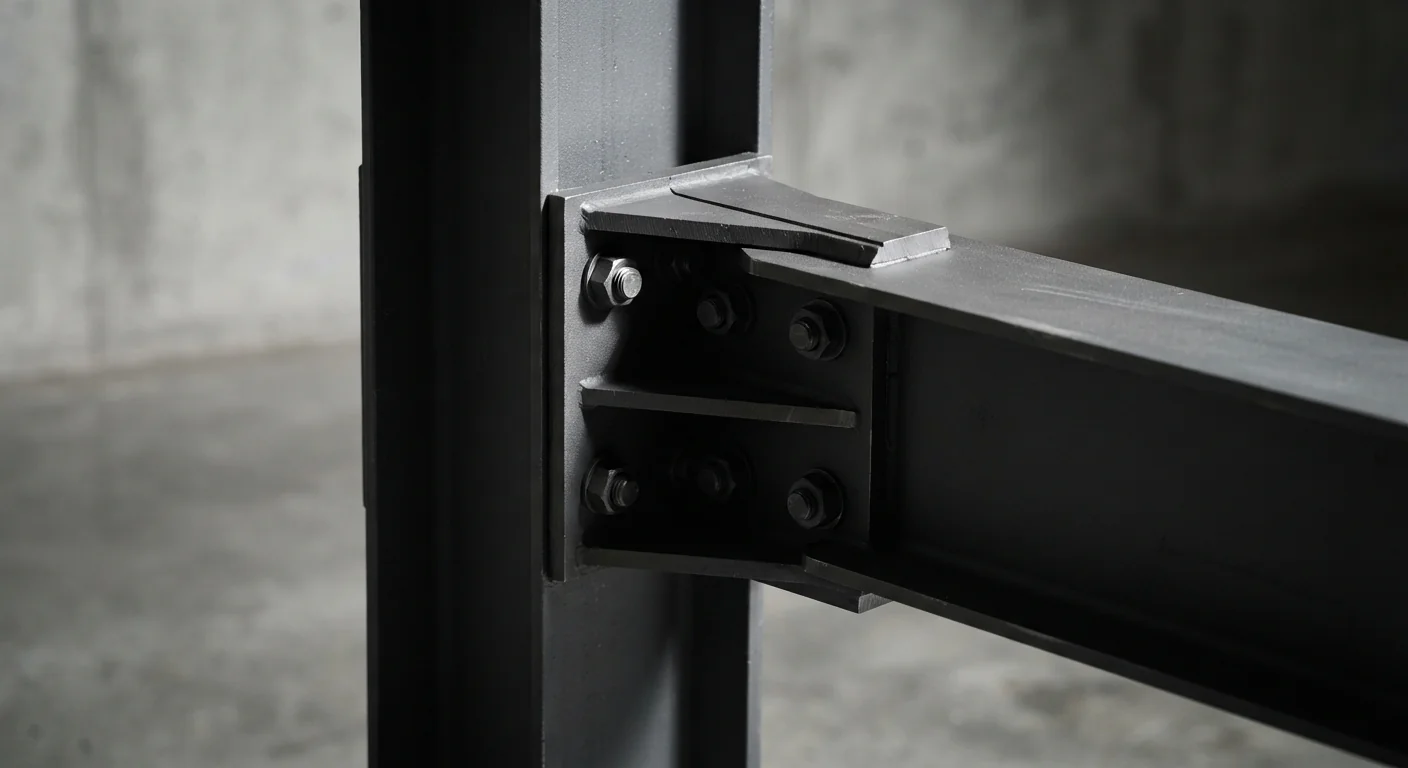
LOD 400: Fabrication-Ready Detail
LOD 400 is where the model stops representing design intent and starts representing exactly what gets built, including assembly, fabrication, and installation detail. An LOD 400 curtain wall model does not just show glazing panels of the right size; it shows the actual mullion profile, gasket geometry, and anchor spacing that a fabricator will cut metal to. This level is typically produced by the specialty contractor or fabricator, not the architect of record, because it requires shop-specific manufacturing data the design team does not control. Architects still play a role: reviewing LOD 400 submittals against the design intent model to confirm nothing was value-engineered away in translation. Requesting LOD 400 from the outset for an entire building is rarely justified, since it demands detail resolution before design decisions in unrelated areas have even been finalized.
- Fabrication-specific geometry: exact profiles, connection hardware, and material gauges
- Assembly sequencing information for shop and field installation
- Manufacturer or supplier-specific product data, not generic placeholders
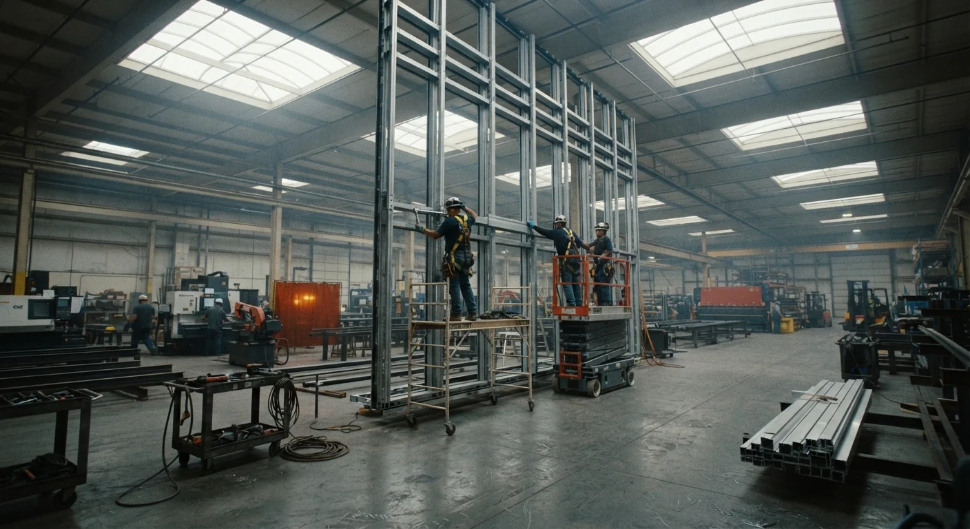
Where the Real Differences Show Up Between the Two Levels
The practical gap between the two levels is not visual completeness, it is who can rely on the model for what decision. An estimator can take reliable quantities off an LOD 300 model for budgeting; a fabricator cannot cut material from it without further shop drawings. Conversely, an LOD 400 model is often too granular and too fragmented across trade-specific files to serve as a single source of design coordination, since each fabricator models only their own scope in isolation. Contract language should specify LOD by element category and by project phase, not as a single number applied to the whole deliverable, because asking for LOD 400 across an entire model when only the curtain wall and stair systems need that resolution creates unnecessary cost and schedule risk for everyone involved, including consultants who then have to model placeholder geometry at a detail level their scope was never meant to carry.
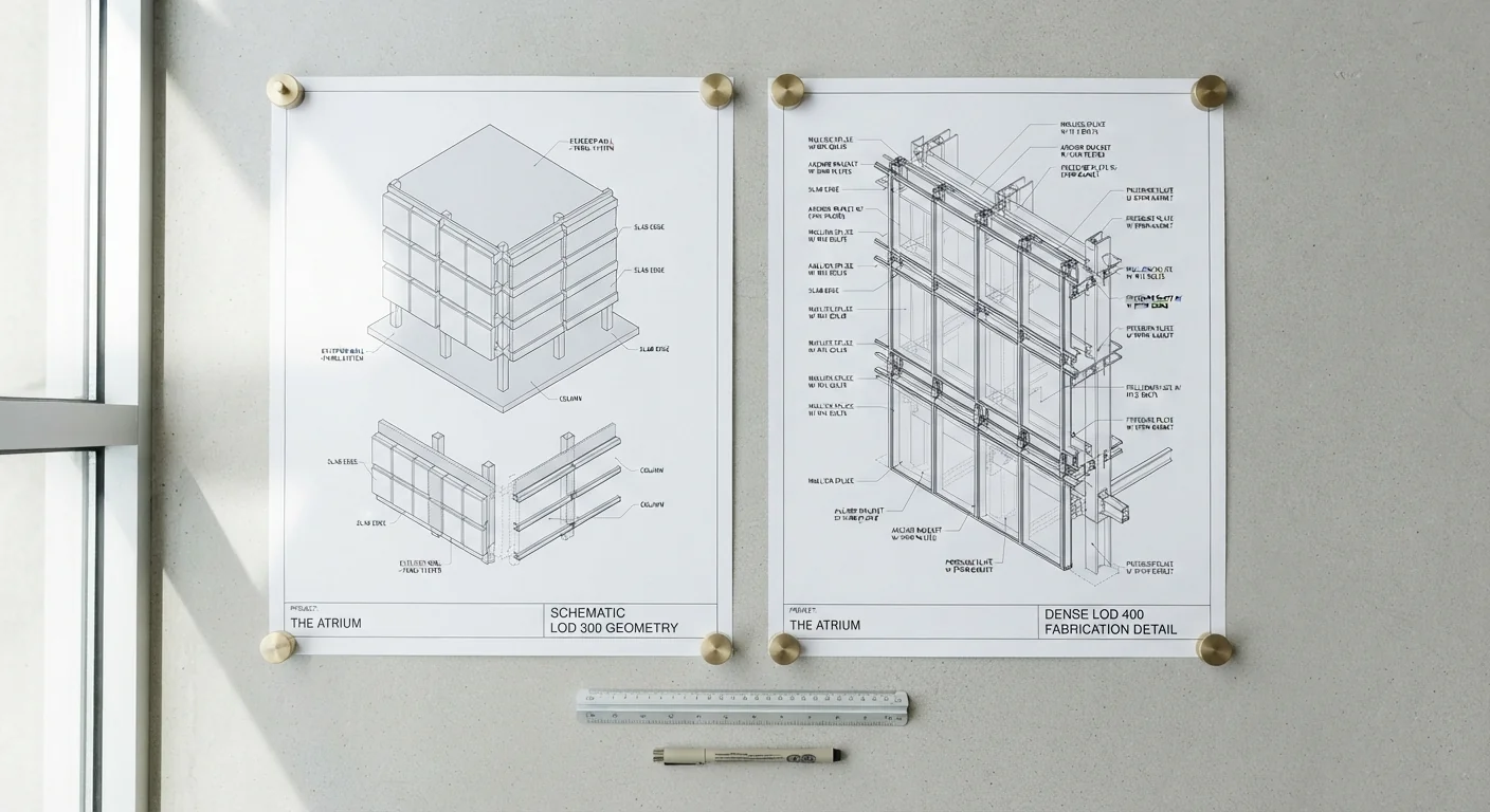
Who Decides the LOD, and When
LOD requirements belong in the BIM execution plan, agreed before modeling starts, not negotiated element by element mid-project. AIA E203 and G202 documents, or a project-specific BIM execution plan, should assign target LOD by discipline, by element, and by project milestone, with the general contractor or construction manager typically driving the LOD 350 to LOD 400 transition once a trade is bought out. Architects should resist open-ended requests to model everything at LOD 400 speculatively, since that detail is only valid once a specific product or fabricator has been selected, and modeling ahead of that selection produces geometry that has to be rebuilt anyway. Setting these expectations early, and documenting which party is the model author for information at each level, prevents the common dispute over who is liable when a downstream trade relies on detail the architect was never contracted to provide.

Common Mistakes Teams Make With LOD Requirements
The most frequent mistake is treating LOD as a single project-wide setting rather than an element-by-element specification, which either under-delivers critical interfaces or over-delivers unnecessary detail elsewhere. A close second is confusing LOD with level of detail, a related but distinct concept describing visual graphic content rather than reliability of information; a highly detailed-looking model can still be low LOD if the geometry cannot be relied upon for measurement or fabrication. Teams also frequently skip LOD 350 entirely, jumping from LOD 300 design coordination straight to expecting LOD 400 fabrication submittals, which leaves the connection and interface coordination step undone and surfaces as field conflicts instead. Finally, many execution plans specify LOD at design milestones but never revisit it as trades are bought out, so the model’s actual reliability quietly diverges from what the contract documents claim it to be.

Frequently Asked Questions
What is the main difference between LOD 300 vs LOD 400 in a BIM model?
LOD 300 elements are accurately sized, located, and oriented for design coordination and quantity takeoff, while LOD 400 elements add fabrication-specific detail like connection hardware and manufacturer data. The BIMForum LOD Specification defines this distinction per element, not per model, so a single project file often mixes both levels across different building systems.
Does LOD 350 replace the need for LOD 400 submittals?
No, LOD 350 only adds interface and connection geometry to resolve coordination between trades; it does not carry the shop-specific fabrication data LOD 400 requires. Contractors typically request LOD 350 during design coordination and reserve LOD 400 for the fabricator’s actual shop drawings after a trade has been bought out.
Who is responsible for modeling elements at LOD 400?
LOD 400 modeling is usually produced by the specialty contractor or fabricator, since it requires manufacturer-specific product and assembly data the design architect does not control. The architect’s role shifts to reviewing those submittals against the original design intent model, which is worth scoping early through a consultation at https://wa-associates.com/book-a-consultation/.
Can a permit set be issued from an LOD 300 model?
Yes, most jurisdictions review permit sets built from LOD 300 information because it provides accurate sizing, location, and system identification without requiring fabrication detail that has not yet been contractually locked in. Reviewers are checking code compliance and general arrangement, not shop-level connection geometry, so LOD 300 is typically sufficient at this stage.
Is level of detail the same as level of development in BIM?
No, level of detail describes how much visual and graphic information an element shows, while level of development describes how reliable that information is for real decisions like measurement or fabrication. A model can look highly detailed and still be unreliable if it has not reached the corresponding BIM model detail levels, which is why execution plans should specify development level, not visual polish.
Conclusion
Matching model reliability to the decision being made with it, rather than how finished the geometry looks on screen, is the real skill behind reading any LOD callout. Specify LOD by element and by milestone in the BIM execution plan, expect LOD 350 to carry the coordination load between design and fabrication, and treat LOD 400 as a fabricator’s deliverable to review rather than a default target for the whole model. Teams that get this sequencing right spend less time on RFIs and more time building from information they can actually trust.
Written by Arch. Asiya Faheem Ansari — Principal Architect & Interior Designer, WAA