Revit family creation follows one reliable sequence: plan the family, pick the right template, build a skeleton of reference planes, label dimensions as parameters, flex that skeleton, and only then attach geometry to it. Most first families that break were built in the opposite order, with a nice-looking shape modeled first and dimensions added afterwards, so the geometry has nothing stable to follow when a size changes. This guide walks through the sequence Autodesk’s own help documentation recommends for loadable families, explains what each step protects you from, and finishes with the beginner mistakes worth checking before a family ever reaches a live project.
System, Loadable and In-Place: Which Kind Are You Making?
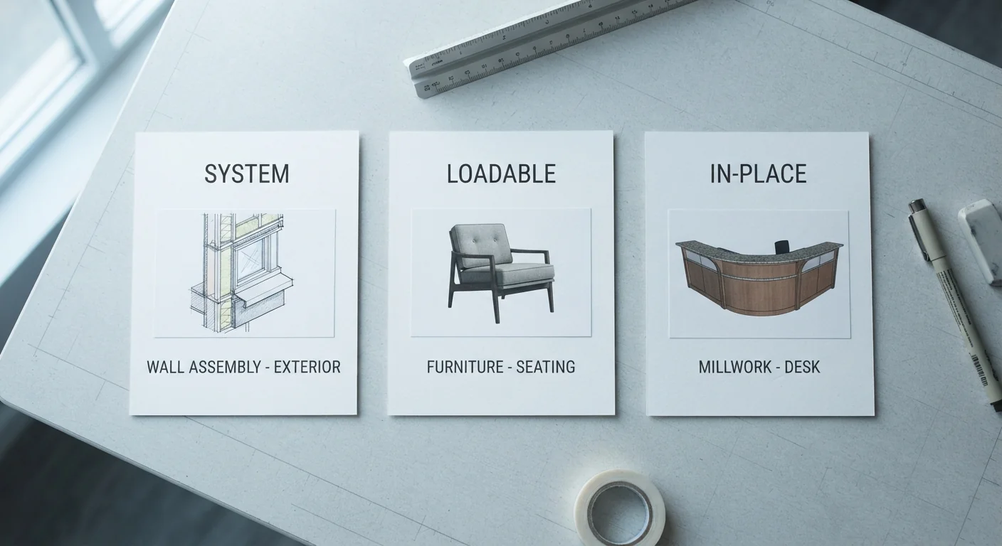
Before any step-by-step work, it helps to know which of the three kinds of families you are dealing with. Autodesk’s help on the different kinds of families (https://help.autodesk.com/cloudhelp/2026/ENU/Revit-Model/files/GUID-403FFEAE-BFF6-464D-BAC2-85BF3DAB3BA2.htm) separates them clearly. System families, such as walls, roofs, floors, ducts and pipes, are predefined in Revit; you do not load them from external files, you create new types of them inside the project. Loadable families are saved as separate RFA files and loaded into projects; they cover things that are usually purchased and installed, such as doors, windows, furniture, fixtures and equipment, plus customised annotation such as symbols and title blocks. In-place families are one-off elements built inside a single project, and each one contains only a single type. This guide focuses on loadable families, because they are the kind you most often create yourself, and because the same Family Editor skills carry over directly to in-place work later.
- System: walls, floors, roofs, ducts, pipes; new types made in the project
- Loadable: doors, windows, furniture, equipment; saved as RFA files
- In-place: one-off, project-specific elements with a single type
Step 1: Plan the Family Before You Open the Editor
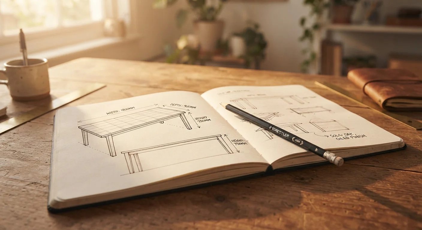
Autodesk’s planning checklist asks a handful of questions that decide everything that follows, and answering them on paper first saves rebuilding later. Will the family need multiple sizes? A bookshelf that comes in any length should be a parametric loadable family, while a single custom piece that only exists once may be better as an in-place element. How should it display in plan, elevation and section, and at which detail levels? Does it need a host? Windows, lighting fixtures and similar objects that sit in or on another element need a host-based template, while furniture can be standalone. How much detail should be modeled? A wall outlet seen only from a distance needs far less geometry than a door that will appear in a close interior rendering. Finally, where is the insertion point? A column family might insert at the centre of its base. For a first exercise, a simple standalone table with width, depth, height and a material is ideal: no host, clear dimensions, and easy to flex.
Step 2: Choose the Right Template and Save the File
A new loadable family starts from File tab, New, Family, which opens the New Family – Select Template File dialog showing the imperial or metric templates for your installation. The template is not a cosmetic choice. Autodesk describes it as the building block that contains the information Revit needs to place the family in projects. Wall-based, ceiling-based, floor-based and roof-based templates are host-based, which means the family can only be placed where that host exists, and each wall-based template includes a wall so you can see how the component fits in or on it. Standalone templates suit objects that are not host-dependent, such as furniture and appliances. For the practice table, choose a standalone template whose category matches the object. Name the family so it describes the element clearly, because that name appears in the Project Browser and Type Selector. Autodesk also advises not saving it to a shared location until the family is complete and tested.

Step 3: Set the Origin and Lay Out Reference Planes
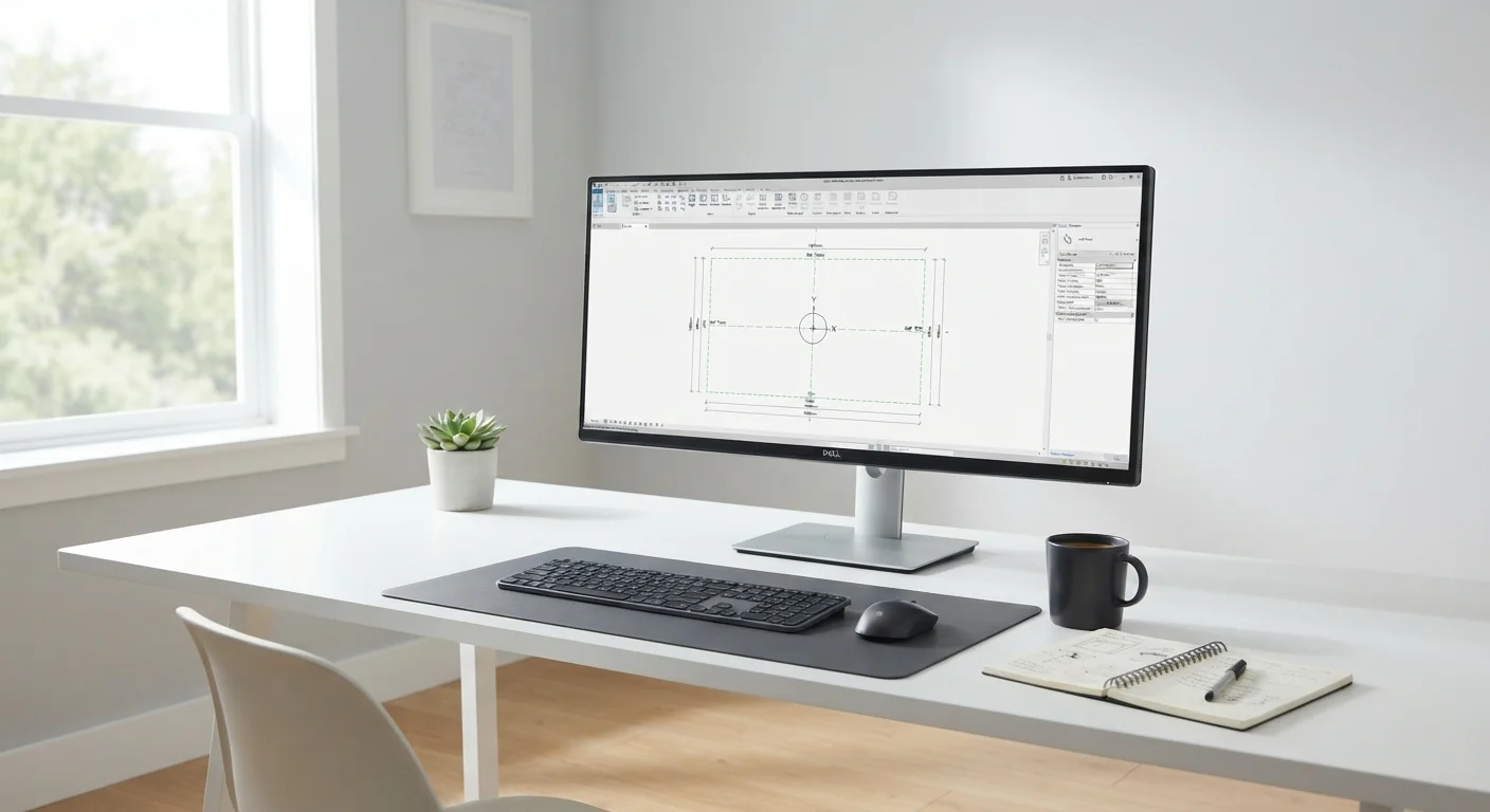
When the template opens, you will usually see two or more dashed green lines. These are reference planes, and together they define where the family inserts. Select them and check the Defines Origin property on the Properties palette; if two intersecting planes already have it, the origin is set. Autodesk recommends keeping that intersection at the family’s internal 0,0 point and pinning the planes so they cannot be moved accidentally. Next, add the skeleton. Use Create tab, Datum panel, Reference Plane to sketch planes for each edge the family needs, for example left, right, front, back and top for the table. Give every plane a name under Identity Data on the Properties palette, so you can pick it later as a work plane. Then set each plane’s Is Reference property. A strong reference is what users will dimension and snap to first once the family is placed in a project, a weak reference needs the Tab key to select, and not a reference cannot be dimensioned at all.
Step 4: Dimension the Planes and Label Them as Parameters
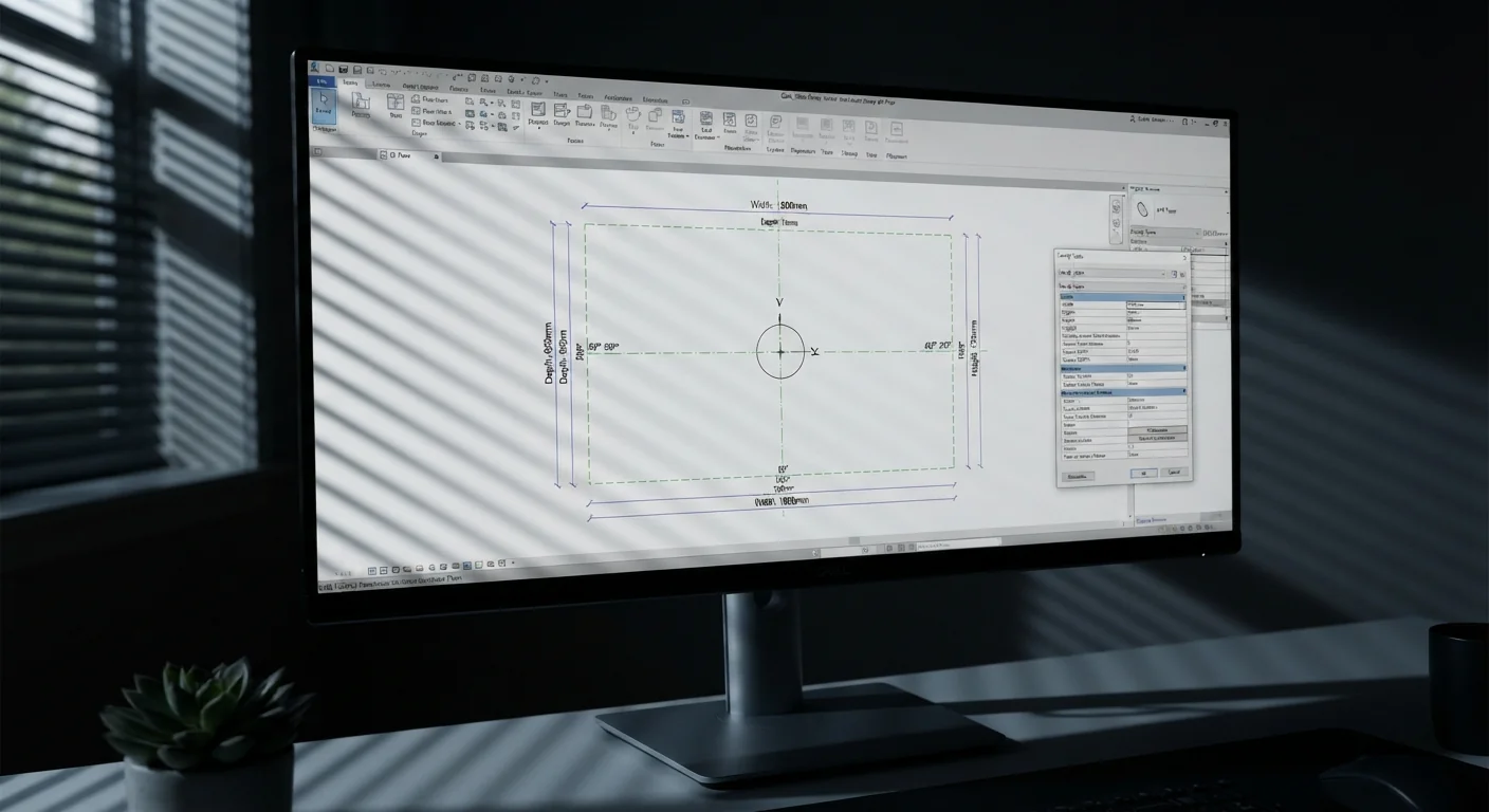
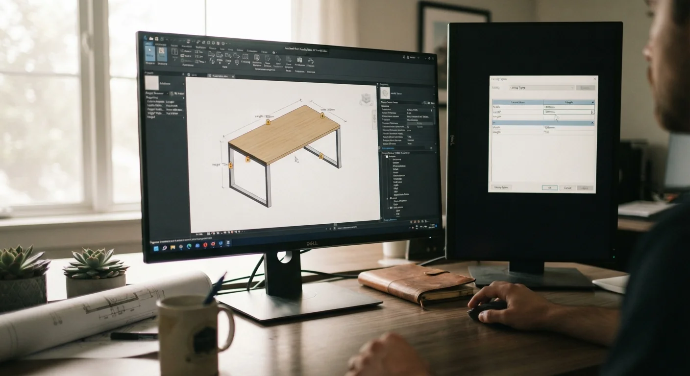
Reference planes only become parametric once they are dimensioned and labelled. Place aligned dimensions between the planes, for example left to right for width and front to back for depth, and between the level and the top plane for height. Then select a dimension and use the Label Dimension panel: choose an existing parameter or click Create Parameter. This is where you decide between a type parameter and an instance parameter, and it is worth deciding deliberately. Type parameters change every placed copy of that type at once, which suits catalogue sizes such as a 1200 by 600 table. Instance parameters change only the selected element, and Autodesk notes that shape handles in the project are only created on instance parameters attached to strong or weak references. Once parameters exist, the Family Types dialog lets you edit their values and add formulas, for example making leg inset depend on table width. Keep the parameter names plain and consistent, because they will appear in schedules and in the Properties palette for everyone using the family.
Step 5: Flex the Skeleton, Then Build and Lock the Geometry
Before drawing a single solid, flex the framework. Open the Family Types dialog, change width, depth and height to very different values, and check that the reference planes move as expected. Autodesk’s best-practice sequence is exactly this: lay out planes, add labelled dimensions, test that the planes flex, and only then place geometry on that flexible skeleton. Now create the geometry with the Family Editor forms: extrusion, blend, revolve, sweep or swept blend, and voids to cut solids. For a table, one extrusion for the top and one per leg is enough. While sketching, use the Align tool to align each sketch line to its reference plane and click the padlock to lock the constraint. The important rule from the documentation is that constraints between pieces of geometry behave unpredictably when parameters change, so lock geometry to reference planes, reference lines or levels, never to other geometry. Flex again after every new solid, because an error is much easier to trace when only one element has changed since the last test.
Step 6: Create Family Types and Test in a Real Project
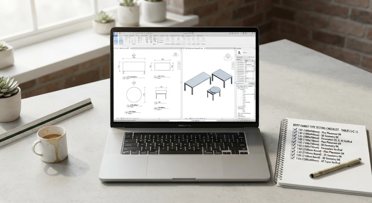
With a family that flexes cleanly, add types. Use Create tab, Properties panel, Family Types, click New, name the type, and enter its values, for example separate types for a 1200 by 600 and a 1600 by 800 table. You can also fill standard parameters such as Material, Manufacturer and Type Mark here. Then test outside the Family Editor. Autodesk’s testing guidance is thorough and worth following as a checklist: load the family into a test project, place each type, and inspect it in plan, reflected ceiling plan, elevation, section and 3D at Coarse, Medium and Fine detail levels, and across visual styles such as Hidden Line, Shaded and Realistic. Check that the preview image uses the preview view, that shape handles move reference planes rather than raw geometry, and, for hosted families, that the family adjusts when the host thickness changes. Only after this pass should the file move to a shared library where colleagues can use it.
- Place every type in a test project
- Check plan, ceiling plan, elevation, section and 3D views
- Check Coarse, Medium and Fine detail levels and several visual styles
- Confirm shape handles move reference planes, not raw geometry
Common Beginner Mistakes That Break First Families
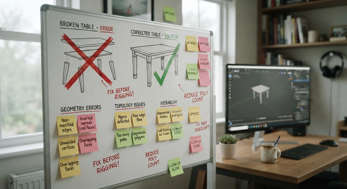
Most failed first families fail for the same handful of reasons, and each one maps back to a step above. Modeling geometry first and adding dimensions afterwards leaves nothing stable for the shape to follow. Locking sketch lines to other geometry instead of reference planes creates constraints that behave unpredictably as soon as a parameter changes. Choosing the wrong template is harder to recover from than it looks: a family started on a host-based template can only be placed where that host exists, so a light fixture intended for open-ceiling spaces may refuse to place. Skipping the origin check leads to families that insert at an unexpected point instead of where the user clicks. Leaving reference planes unnamed, or leaving Is Reference at a default that users cannot dimension to, makes the family frustrating in documentation. Using instance parameters for catalogue sizes causes inconsistent sizes across a project. Over-modeling detail that will never be seen costs authoring time for no visible benefit. Finally, publishing to a shared library before testing spreads the problem to every project that loads it.
Frequently Asked Questions
What is the first step in Revit family creation?
The first step is planning, before you open the Family Editor. Decide whether the object needs several sizes, whether it needs a host such as a wall or ceiling, how it should display in each view, how much detail it needs, and where its insertion point sits. Those answers decide the template, the reference planes and the parameters you build next.
Can beginners create Revit families without any programming?
Yes. You can create Revit families entirely with the Family Editor’s standard tools: reference planes, labelled dimensions, parameters and solid or void forms. Formulas in the Family Types dialog are optional and use simple arithmetic between parameters, not code. Programming tools such as Dynamo only become useful later, when you want to automate repetitive family or model tasks.
What makes a parametric Revit family different from a static one?
A parametric Revit family has its geometry locked to reference planes that are driven by labelled dimensions, so changing a parameter such as width resizes the element correctly. A static family has fixed geometry and needs a new file for every size. The parametric approach lets one family hold several types, each with its own set of values.
What should a good Revit family tutorial cover for beginners?
A good Revit family tutorial should cover template choice, origin, reference planes, labelled parameters, flexing before geometry, family types and testing in a project, plus the common constraint mistakes. Guided online BIM training via Revit, such as the programmes at https://wa-associates.com/waa-skill-studio/, gives structured, lesson-by-lesson practice for learners who prefer not to piece skills together from scattered videos.
When should you use an in-place family instead of a loadable family?
Use an in-place family for a unique element that exists only in the current project and needs to respond to surrounding geometry, such as a custom reception desk shaped to one room. Use a loadable family when the object repeats, comes in several sizes, or could be reused on other projects, because in-place families hold only a single type.
Conclusion
Good Revit family creation is less about modeling skill and more about order: plan, template, origin, reference planes, labelled parameters, flex, geometry, types, test. Following that sequence on a simple table teaches every habit that later families, from doors to equipment, depend on. For learners who want structured practice with Revit beyond a single tutorial, WAA Skill Studio offers online BIM training via Revit.
Written by Arch. Asiya Faheem Ansari — Principal Architect & Interior Designer, WAA